Introduction
The following sections will show a detailed view at installing TOP Server V6, as well as creating a channel, device and tag. Finally, the guide will show you how to test a tag with the built in OPC Quick Client to ensure device connectivity.
Step 1: Install TOP Server V6
- Double click on the topserverv6demo.exe to open the TOP Server V6 installer.
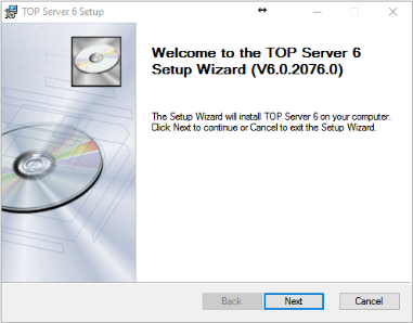
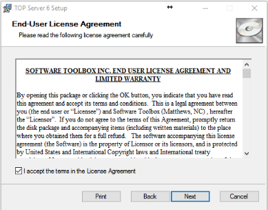
Click Next to begin the install of TOP Server 6. - Read the End User License Agreement, then check the box to accept the terms and click Next
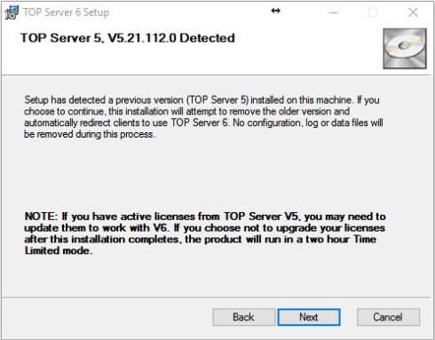
- If you already have TOP Server 5 installed on the machine, it will remove the older version and automatically redirect your clients to use TOP Server 6.
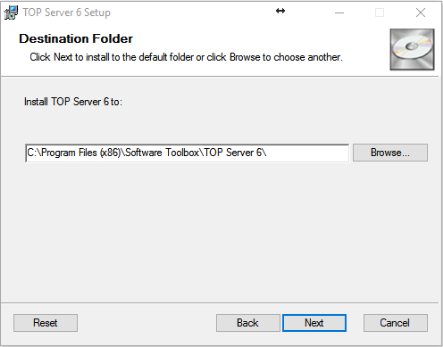
- In the next step, you will select the Destination folder that TOP Server V6 will install too. We recommend leaving this at the default location. Click Next.
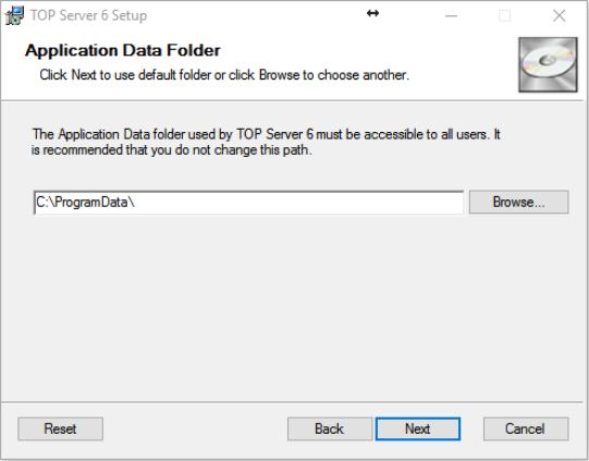
- Select the Application Data Folder. By default, this is set to the C Drive’s Program Data folder. We recommend that you do not change this path. Click Next.
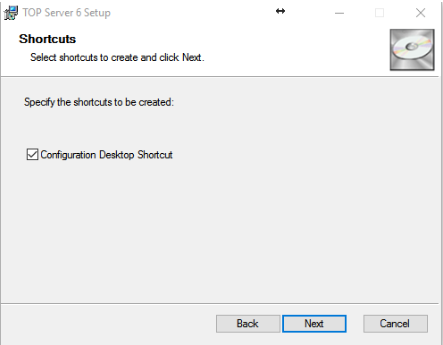
- Leave the box checked if you want a desktop shortcut to the TOP Server configuration. Click Next.
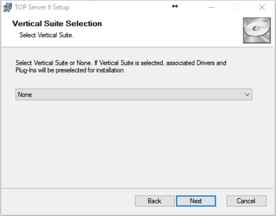
- TOP Server V6 offers Vertical Suite license packages. If you purchased one of the vertical suites, you can select the suite from the drop-down list. This will automatically select your drivers for install in the next step. If you are unsure, or did not purchase a vertical suite, select None and click Next.
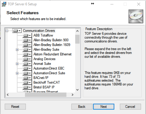
- You will now select the features that you want to install with TOP Server V6. If you are evaluating the software, you may want to install the Full Installation.
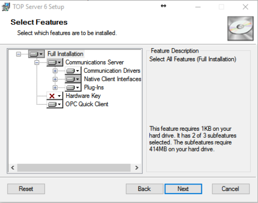
- TOP Server has hundreds of communication drivers in a single install package. You may individually select which drivers you want to install under the Communication Drivers tree.
- If you plan on using Wonderware InTouch with TOP Server, you will want to install the Wonderware SuiteLink and FastDDE components under Native Client Interface. You will also find DDE and OPC.NET drivers under this branch.
Once you have selected all your needed drivers, click Next.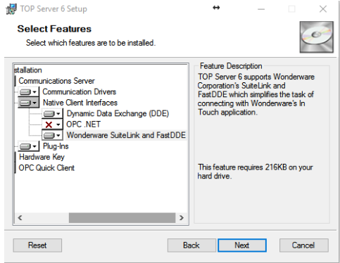
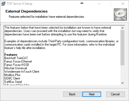
- The next screen will show a list of External Dependencies. Please contact your vendor for configuration tools, communication libraries, or communication cards if needed.
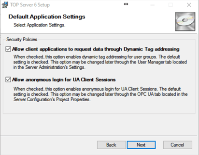
- The default security policy, Allow client applications to request data through Dynamic Tag Addressing, should be left checked if you intend to Dynamically address your tags through your client application, such as Wonderware InTouch. The other security default is Allow anonymous login for UA Client Sessions. You may change either of these options later in the TOP Server configuration. Click Next.
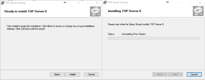
- You are now ready to Install TOP Server 6. Click Install. If TOP Server version 5 is installed, it will uninstall at this time as well.
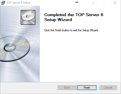
- You have finished installing TOP Server 6.
Step 2: Configuration
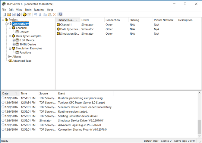
TOP Server will open loaded with a sample simulation project by default.
If the sample configuration is not loaded on TOP Server, you can click on File, then Open, navigate to C:\Program Files (x86)\Software Toolbox\TOP Server 6\Projects, and open the simdemo.opf
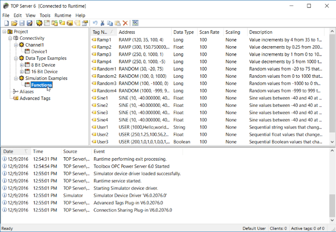
When the file is open, the TOP Server screen will show the above in the tree view. By default, the configuration is connected to the Runtime – as seen up at the title bar. Any changes made are committed to the runtime as soon as you make them.
To work offline and then update the runtime after all changes have taken place, click on Runtime then Disconnect on the TOP Server menu. To commit changes to runtime, click Runtime and then Connect. TOP Server will then prompt for changes to be saved and ask to update the Runtime with the changes.
In the Simulation project under Connectivity, there are 3 channels configured with a total of 4 devices.
A Channel corresponds to a communications port for serial connections or a single thread of execution for Ethernet connections. Under each channel, provided the PLC protocol being used supports multi-drop, multiple devices can be configured. For example, there are two devices configured under the Data Type Examples channel. A Device is a PLC or piece of hardware.
When clicking on a device name, such as Functions, the right-hand pane will populate with a list of tags. In the simulation project example, some tags are pre-configured.
Each tag corresponds to a single memory location in the PLC or device. Tags can be added by right clicking on the device name and selecting New Tag. Tags may also be added by right clicking in the window pane, where tags are shown, and selecting New Tag.
Valid memory addresses for the Simulation Driver:
- K0 to K9999 - tags that users can read/write values to - can be configured as any memory type
except Boolean. Attach a .Bit Number suffix to create a Boolean tag - for example, K0.03 is the 4th
bit (bits numbered 0 to 15) in the word 0 in the K memory area. - R0 to R9999 - tags that users can read/write from that is constantly updated with incrementing
integer data so you have data that changes - can be configured as any memory type except
Boolean. Attach a Bit Number suffix to do a Boolean tag - for example R0.03 is the 4th bit (bits
numbered 0 to 15) in the word 0 in the R memory area - S0 to S999 - String tags - you can read/write strings from these tags
- Ramp, Sine, Random, User - tags that can be configured to simulate data based on configuration.
Step 3: Launching the Quick Client
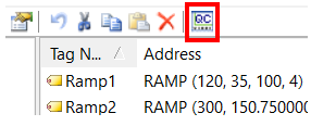
Launch the OPC Quick Client at any time by clicking on the Quick Client button on the toolbar of TOP Server.
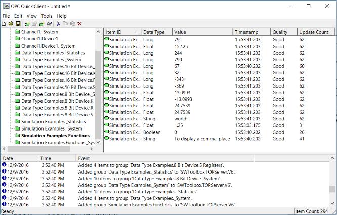
When the Quick Client launches, it will automatically connect to TOP Server, browse for available tags, subscribe to tags, and start displaying the live data.
Once launched, the Quick Client icon will show on the taskbar.
Each time the Quick Client icon is clicked, another instance of the Quick Client is launched as there is no hard-coded limit on the number of clients you can have simultaneously connected to the TOP Server 6. Quick Client automatically connects to TOP Server 6 with a 1000 ms update rate. Change the default group update rate in Quick Client by clicking Tools ⇒ Options.
The Quick Client can also be started directly by clicking Start ⇒ Programs ⇒ Software Toolbox ⇒ TOP Server 6 ⇒ Quick Client. The Quick Client can connect to any OPC Sever, create a group, and browse for tags - a great tool for troubleshooting!
After the Quick Client is launched, different values can be written to a tag by right clicking and choosing from Synchronous Write or Asynchronous 2.0 Write. The value for tags that reference the R register in the simulation driver is over-written by the simulated data as soon as the new value is written. For example, if the tag original value is 2359 when a 0 is written the simulator will automatically keep counting from 0 after the write is performed.
To control how fast individual groups are polled right click on one of the folders in the left-hand pane then click Properties. This can be a key adjustment when connected to a physical device.
Step 4: Configuring a Channel
After seeing the simulation demo, most users are ready to configure a channel and create a project tailored to their specific devices.
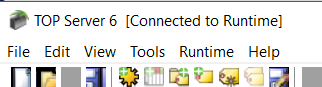
The TOP Server 6 title bar will show TOP Server 6 [Connected to Runtime] when connected to the runtime service. This indicates that any changes are made live in the server. The following steps will create a project offline and then upload the new configuration to the runtime.
Click File ⇒ New to from the TOP Server 6 menu. A prompt will appear with the option to update the current runtime project or to edit offline
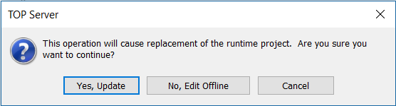
For this guide, click No, Edit Offline to create a new configuration without uploading to the current runtime. By clicking Yes, Update the runtime project is immediately replaced with the new configuration and all changes are made in an Online Configuration Mode.
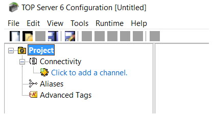
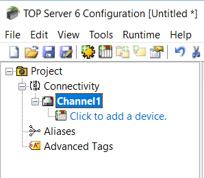
The TOP Server 6 title bar will now change to read TOP Server 6 Configuration [Untitled].
Once the new project is created, click File ⇒ Save to save with a specific filename. The project file will end in .opf
- Click on Click to add a channel. This will open the Add Channel Wizard
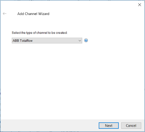
- Select the type of channel to be created by selecting the device driver. The device driver is the protocol being used to connect to the device. The drop down box will only display the device drivers that were installed. If no device drivers exist, then the TOP Server 6 installer will need to run again and the device drivers will need to be selected and installed.
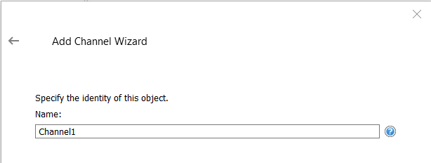
- Specify a name for the channel
- Depending on the channel type, selected the channel property options will vary. These channel properties should be configured to communicate with the device per the hardware specification, and serial/Ethernet connection. Once the channel is created, these properties can be modified. The TOP Server 6 help files go into further detail on channel properties specific to device drivers.
- Review the summary for the new channel and choose Back to make changes or Finish to close.
Step 5: Configuring a Device
In Step 4 above, a channel was configured to speak the language of the device. In Step 5, a new device will be created in TOP Server 6. This device creation allows communication to a specific device on a channel. Please view the specific device driver help file to see if multiple devices per channel are supported. When using an Ethernet channel, communications can be optimized by only creating one device per channel.
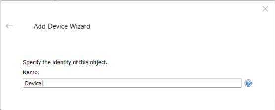
- Click Click to add a device located underneath the created channel.
- Specify a name for the device
- Select the specific type of device – see the help file for the specific device driver for further detail on which device model to choose.
- Specify the devices driver-specific station or node ID. For most Ethernet communications, the device IP Address will be used. The device driver specific help file will contain further detail on formatting the address for the device.
- Each device has specific settings which are explained in more detail in the device driver help file. The section of the help file can be accessed directly by clicking the question mark located in the blue circle.
- Once finished, look through the summary of the device and click Finish.
Step 6: Configuring a Tag
TOP Server offers the ability to configure optional groups and subgroups to provide multi-level organization of tags. Tag groups allow you to tailor the layout of OPC data in logical groupings that fit the needs of your application.
Using tag groups allows multiple sets of identical tags to be added under the same device. This can be very convenient when a single device handles several similar machine segments. From an OPC client standpoint, the use of tag groupings allows you to segregate your OPC data into smaller tag lists, which can make finding a specific tag easier when browsing the server.
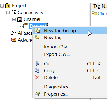
To add a new tag group to your project, right click on either an existing device or tag group branch and select "New Tag Group" from the context menu.
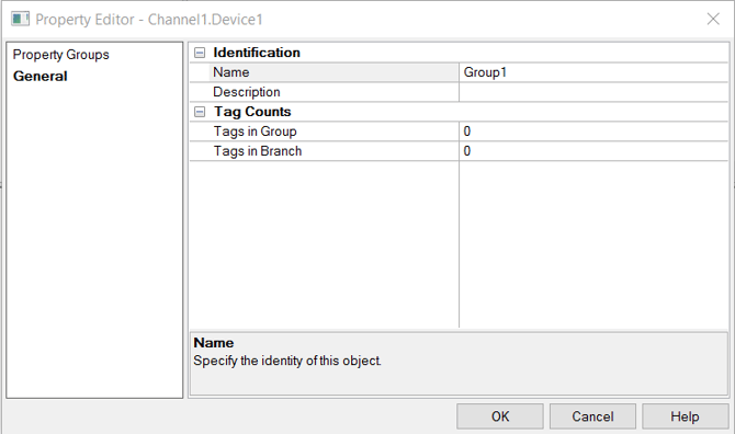
Once opened, a properties window will display. Enter a name for the tag group, and how many tags in the tag group.
A single static tag may also be created.
Please note that Tags are not required if your Client can support the device memory address in its tag database. TOP Server supports dynamic tags. More information can be found regarding Aliases and static and dynamic tags in the server help file.
It is recommended that at least one valid tag is configured for each device so that communications may be confirmed with the OPC Quick Client.
Right click on Device 1 and click New Tag, or click in the right-hand pane where the text reads “Click to add a static tag.”
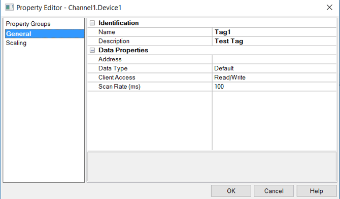
- Enter a tag Name and Address. The tag name can be any meaningful name, while the address must be the correct syntax for the device memory address.
- You may click on “…” in the Address row to see the possible accepted syntax for the device addresses. To access the “…” click in the address box to the right of Address.
- It is recommended to leave the Data Type at Default, unless a device that uses multiple Word or Byte addresses to support larger data types such as floats is being used.
- The Scan Rate is only used with DDE type connectivity and does not need to be set if you’re not using DDE.
- If the tag needs to be scaled, click on the Scaling item under Property Groups to set the scale of the tag.
Once a tag is created, the Quick Client can be opened to see the tag in action.
TOP Server Plug-In Configurations
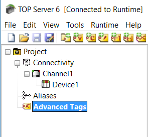
TOP Server offers several optional Plug-Ins, in addition to drivers. These Plug-Ins are displayed under the Project and are listed after Aliases.
Plug-Ins, just as in drivers, must be installed during the installation process. For this guide, Advanced Tags is the only Plug-In shown in the below screenshot.
Currently we offer Advanced Tags, OPC Alarms & Events, Data Logger, EFM Exporter, Local Historian, Scheduler Plug-In and an SNMP Agent plug-in
To configure a Plug-In, right click on the name of the Plug-In and select a feature to configure. Each Plug-In has specific settings which can be read in more depth in the Plug-In help file.